Sheet metal bend allowance calculator
Enter thickness, inside radius, K-factor and bend angle to get the bend allowance, bend deduction and flat blank length. Or bend a test strip and back out your real K-factor.
STEP · STL · IGES · DWG · DXF · SLDPRT · and more
No CAD file? Describe your project instead
90 for an L. Not the included angle.
Typical for this R/T:
Flat length
2.8957in
Bend deduction
0.1043in
Bend allowance
0.1357in
Outside setback
0.12in
Flanges are outside dimensions to the virtual sharp. Results are a starting point; your shop's press brake and tooling set the final flat pattern.
Bend allowance is the length of the neutral axis through a bend: the amount of flat material a bend uses up. Bend deduction is how much shorter the flat blank is than the sum of the outside flange lengths. Both depend on material thickness (T), inside bend radius (R), bend angle and the K-factor, which locates the neutral axis as a fraction of thickness from the inside surface.
The calculator uses the standard press-brake formulas below. Treat the result as a starting point: the shop that forms the part sets the final flat pattern from its own tooling and test bends.
Bend allowance and bend deduction formulas
With the bend angle θ in radians (degrees × π / 180):
- Bend allowance: BA = θ × (R + K × T)
- Outside setback: OSSB = tan(θ / 2) × (R + T)
- Bend deduction: BD = 2 × OSSB − BA
- Flat length (one bend): flat = A + B − BD, where A and B are the outside flange lengths to the virtual sharp
The bend angle here is how far the flange moves from flat, so an L bracket is a 90° bend. If your drawing calls out the included angle, the bend angle is 180° minus it.
| Term | Formula | What it is |
|---|---|---|
| Bend allowance (BA) | θ × (R + K × T) | Neutral-axis arc length through the bend |
| Outside setback (OSSB) | tan(θ/2) × (R + T) | Tangent point to the virtual sharp |
| Bend deduction (BD) | 2 × OSSB − BA | Subtract from the outside flanges |
| K-factor (from a test) | (BA / θ − R) / T | Back-calculated from a measured bend |
What is the K-factor?
When sheet metal bends, the inside compresses and the outside stretches. Somewhere between them is the neutral axis, which keeps its original length. The K-factor is the neutral axis position divided by the thickness: 0.5 means it sits in the middle, smaller numbers mean it has shifted toward the inside of the bend.
K-factor changes with the ratio of inside radius to thickness, the material and temper, and the forming method. Tight bends push it lower. The values below are common starting points for air bending, not guarantees; a test bend on the shop's brake is how you pin it down. For the smallest radius each material tolerates before cracking, see the sheet metal bend radius chart.
| Inside radius vs thickness | Typical K-factor (air bending) | Notes |
|---|---|---|
| R less than T | about 0.33 | Tight bends; the neutral axis moves toward the inside |
| R between T and 3T | about 0.40 | The usual range for brackets and enclosures |
| R more than 3T | about 0.50 | Large radii approach the middle of the sheet |
Starting points only. Material, temper, grain direction, tooling and the press brake all move the real value.
Typical K-factor by material
Softer, more ductile material keeps the neutral axis closer to the inside of the bend at tight radii, while harder material holds it closer to the middle. These are the widely published typical starting values for air bending, grouped by inside radius (R) to thickness (T). They agree closely with the DIN 6935 correction formula, which gives K ≈ (0.65 + 0.5 × log10(R/T)) / 2 for R/T up to about 5: roughly 0.33 at R = T and 0.44 at R = 3T.
| Inside radius (R/T) | Soft aluminum (e.g. 3003-O, 5052-H32) | Mild steel (e.g. 1008/1010 CRS, A36) | Stainless steel (e.g. 304) |
|---|---|---|---|
| R/T under 1 (tight bend) | about 0.33 | about 0.38 | about 0.40 |
| R/T 1 to 3 | about 0.40 | about 0.43 | about 0.45 |
| R/T over 3 | about 0.50 | about 0.50 | about 0.50 |
| Bottoming, R/T 1 to 3 | about 0.46 | about 0.47 | about 0.48 |
| Coining, R/T 1 to 3 | about 0.44 | about 0.46 | about 0.47 |
Typical values, not guarantees. Temper, grain direction, die opening, tooling, and the specific press brake shift the real K-factor by a few hundredths, which on a multi-bend part adds up. Harder tempers such as 6061-T6 typically need a larger radius and a test bend to set K. Use a test bend or the shop's bend table for production flat patterns.
Worked example
An L bracket in 0.060 in steel with a 0.060 in inside radius, a K-factor of 0.44 and a 90° bend, with outside flanges of 2.000 in and 1.000 in:
- BA = (π / 2) × (0.060 + 0.44 × 0.060) = 0.1357 in
- OSSB = tan(45°) × (0.060 + 0.060) = 0.1200 in
- BD = 2 × 0.1200 − 0.1357 = 0.1043 in
- Flat length = 2.000 + 1.000 − 0.1043 = 2.8957 in
How to find your K-factor with a test bend
- Cut a strip of the exact material and thickness you will use, and measure its flat length.
- Bend it to a known angle on the same tooling the part will use.
- Measure both outside flange lengths to the virtual sharp.
- Switch the calculator to Find K-factor and enter the thickness, inside radius, angle, both flanges and the flat length.
The calculator works out the bend deduction from your strip, then the bend allowance, then the K-factor. Use that K-factor for parts made from that material on that brake.
When to let the shop set the flat pattern
If you send a 3D model with bends, most fabrication shops generate the flat pattern themselves from their own bend tables, which already account for their tooling. That is usually the most accurate option. Send your own flat DXF only when you have matched the shop's K-factor or bend deduction, and say on the drawing which one you used.
Need the parts made? See sheet metal fabrication services or custom metal fabrication.
Parts in 3 steps

Upload your part
A CAD file or a sketch. Free quote in about 24 hours.
We match + manufacture
The best-fit shop from our network makes it, on your timeline.
Receive + review
Inspected, shipped and tracked in your inbox.
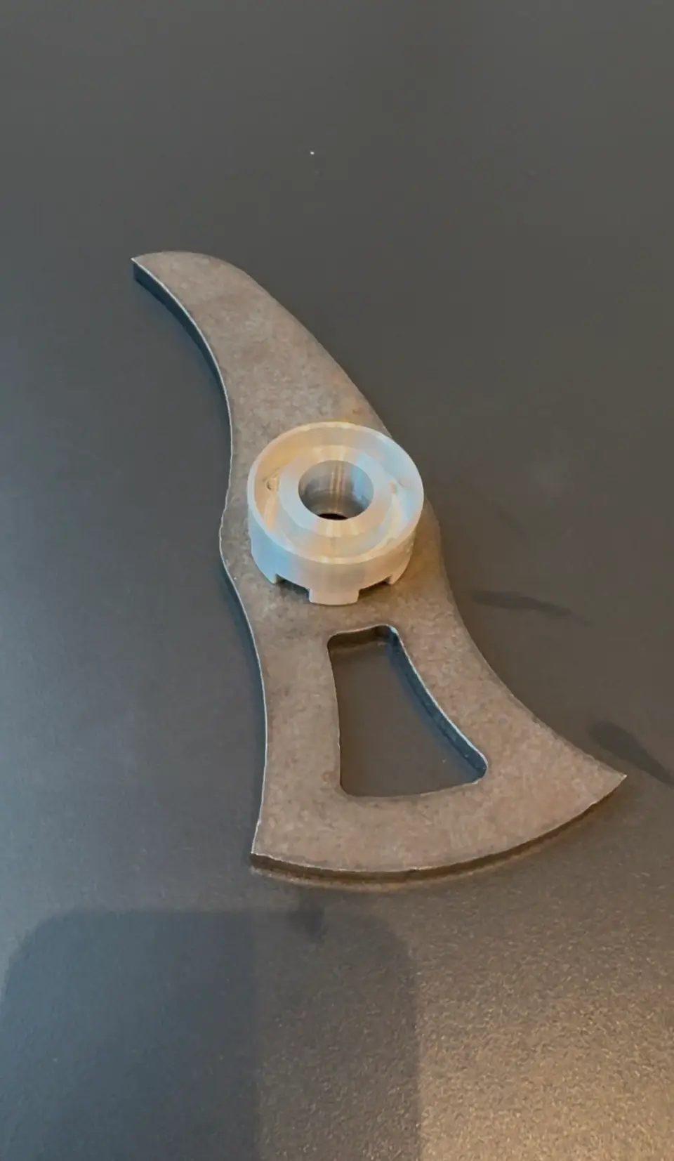
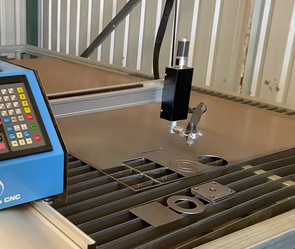
Processes for formed parts
Where the flat pattern goes next.
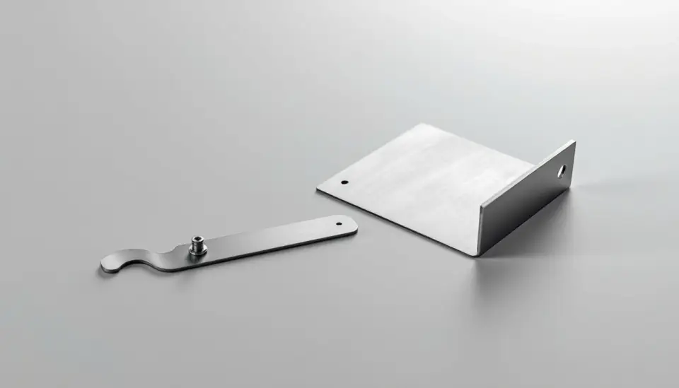
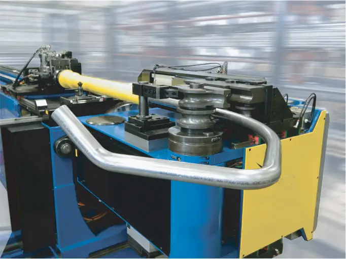
Get quotes for formed sheet metal parts
Upload your model or flat pattern and we source quotes from independent fab shops that cut, bend, weld and finish it as one job.
- Free quote in about 24 hours
- No minimum order
- No account needed to start
STEP · STL · IGES · DWG · DXF · SLDPRT · and more
No CAD file? Describe your project instead
Frequently asked questions
What is the difference between bend allowance and bend deduction?
Bend allowance is the length of material the bend itself uses, measured along the neutral axis. Bend deduction is how much you subtract from the sum of the outside flange lengths to get the flat blank. They describe the same bend from two directions: BD = 2 × outside setback − BA.
What K-factor should I use?
If you do not have a tested value, about 0.33 for bends tighter than the material thickness, about 0.40 for radii between one and three thicknesses, and about 0.50 for larger radii are common air-bending starting points for soft aluminum. Mild steel runs slightly higher at tight radii (about 0.38 to 0.43) and stainless higher again (about 0.40 to 0.45). A test bend on the shop's brake gives the real number.
Is the bend angle the same as the included angle?
No. This calculator uses the bend angle, how far the flange moves from flat, so an L is 90°. The included angle is the angle between the two flanges, which is 180° minus the bend angle. A 135° included angle is a 45° bend.
Does this work in millimeters?
Yes. Switch the units to mm. The formulas are the same in any unit as long as every length uses the same one.
Why does my flat pattern not match the shop's?
Shops calculate flat patterns from their own tooling, material and bend tables, so their K-factor or bend deduction may differ from yours. Send the 3D model and let the shop generate the flat, or ask which value they use and match it.
Can I use this for tube bending?
No. Tube bending uses centerline radius and different allowances for wall thinning and springback. Send the bent tube model to a tube bending shop and they set the cut lengths.
More free tools and charts
Sources
- DIN 6935, Cold bending of flat rolled steel products
Last reviewed by Tom Petrini