Process & DFM
Sheet Metal DFM: The Six Ways a Bent Part Goes Wrong
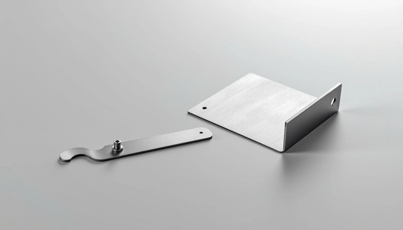
The short answer
Sheet metal parts fail in a small number of predictable ways: the outside of a bend cracks when the radius is too tight, holes near a bend stretch into ovals, short flanges cannot be gripped by the press brake, bends without relief tear at the corner, countersinks near an edge blow through, and hardware pulls out of material too thin to support it. Each common design rule, such as an inside radius of at least one material thickness or holes at least two thicknesses from a bend, exists to prevent one of those failures.
Why sheet metal rules feel arbitrary
Machining rules are about the tool: a cutter has a diameter, so an internal corner has a radius. Sheet metal rules are about the material, because forming does not remove anything. It stretches the outside of a bend, compresses the inside, and moves everything nearby.
That is the whole model. A flat blank is cut, then a punch drives it into a die and the metal deforms permanently. Anything you put near a bend gets dragged into that deformation. Anything you ask the press brake to grip has to be large enough to grip. Anything you bend tighter than the material tolerates cracks on the outside radius.
Work through the six failures below and the rules stop being a list to memorize. You can derive them, and more usefully you can tell when a rule does not apply to your part.
Failure one: the bend cracks on the outside
The outer surface of a bend is in tension. Make the inside radius too small and the outer fibers exceed what the material will take, so the bend crazes, then cracks, usually along a visible line.
The common rule is an inside radius of at least one material thickness, tabulated by material and gauge in the bend radius chart, and for soft aluminum and mild steel at moderate gauges that holds up well. Where it breaks down is material temper. A 5052-H32 aluminum will take a 1T bend comfortably. A 6061-T6 of the same thickness often will not, because the temper that makes it strong also makes it far less formable, and the fix is either a larger radius, a different alloy, or bending in the annealed condition and heat treating after.
Grain direction matters too. Bending across the rolling direction is more forgiving than bending along it. On a part with bends in two directions, this is a real constraint on how the blank is nested, and it is why a shop may quote more material than the part area suggests.
Design response: specify the inside radius rather than leaving it to the shop, keep it at one thickness or more, and if the design demands both high strength and tight bends, say so early. That combination decides the alloy.
Failure two: a hole near a bend turns into an oval
The metal around a bend moves. A hole placed inside that zone gets stretched along with it, and arrives distorted, usually elongated toward the bend and no longer round enough to take a fastener cleanly.
The working rule is to keep holes at least two material thicknesses away from the bend, measured from the edge of the hole to the start of the bend radius, and to be more generous on larger holes and thicker material.
When a hole genuinely has to sit close to a bend, there are two fixes. Extend the hole into the bend deliberately, so it becomes a clean slot that crosses the radius rather than a round hole that gets pulled out of shape. Or punch the hole after forming as a secondary operation, which costs more but holds position.
Design response: treat the area within two thicknesses of any bend as unavailable for features, and lay out the flat pattern with that exclusion zone visible.
Failure three: the flange is too short to bend
A press brake grips the blank and drives it into a die. If the flange is shorter than roughly four times the material thickness plus the bend radius, there is not enough material bearing on the die, so the part slips, the angle wanders, or it cannot be formed at all.
This one surprises people because the part looks fine in CAD. A 4 mm lip on a 2 mm sheet is a drawing, not a bend.
Design response: check every flange against the minimum, and where a short flange is unavoidable, expect it to be formed oversize and machined back, or produced a different way entirely. Both cost more than lengthening the flange by a few millimeters, which usually costs nothing.
Failure four: the corner tears where two bends meet
Where a bend ends against unbent material, the metal has to transition abruptly from deformed to flat, and the stress concentrates at that junction. Without somewhere for it to go, the material tears.
The fix is a bend relief: a small notch cut at each end of the bend line, at least one material thickness wide and extending past the bend radius. It looks like a defect to someone who has not seen it before, and it is the difference between a clean corner and a crack.
The related case is two bends meeting at a corner, where the two deformation zones would overlap. That needs a corner relief, and the shape matters: a round relief distributes the stress better than a square one and is less likely to start a crack of its own.
Design response: add reliefs in CAD rather than leaving the shop to add them, the same way you would add a corner relief for a routed panel. A relief added by the shop is a change to your part, and it will land wherever the CAM operator puts it.
Failure five and six: countersinks and hardware in thin material
Countersinks that break through. A countersink removes a cone of material. Put it too close to an edge or a bend and there is nothing left to support it, so the edge collapses or the cone breaks out. Keep countersinks at least three material thicknesses from any edge or bend, and check that the material is thick enough to contain the full cone depth. In thin sheet, a countersink for a common flat head can consume the entire thickness, at which point the hole is a knife edge.
Hardware that pulls out. Self-clinching hardware, the pressed-in standoffs and nuts often specified as PEM, works by displacing material into an undercut. How it compares to screws, rivets and welding is covered in design for assembly. That needs both minimum sheet thickness and minimum hardness, and it has to be installed on the correct side. Below the minimum thickness the hardware spins or pulls out under load, which shows up during assembly rather than during inspection.
A further constraint people miss: hardware is installed while the part is still flat, or at least while the press can reach. A standoff inside a deep formed box may be impossible to install after forming, which turns a cheap operation into a redesign.
Design response: check the hardware manufacturer's minimum sheet thickness before choosing the gauge, and confirm every piece of hardware can be reached by a press at the point in the sequence where it gets installed.
The rules, in one table
Having worked through the failures, the rules are easy to state. Use them as a check, not as a substitute for understanding which failure each one prevents.
| Feature | Guideline | Failure it prevents |
|---|---|---|
| Inside bend radius | At least 1x material thickness, more for hard tempers | Cracking on the outside of the bend |
| Hole to bend distance | At least 2x thickness from the bend radius | Holes stretched into ovals |
| Minimum flange length | About 4x thickness plus the bend radius | The brake cannot grip the flange |
| Bend relief | At least 1x thickness wide, past the radius | Tearing where the bend ends |
| Corner relief | Rounded, sized to the two bend zones | Cracking where two bends meet |
| Countersink to edge | At least 3x thickness | Blow-out and collapsed edges |
| Hole diameter | At least 1x thickness, larger in thick material | Punch breakage and torn holes |
| Bend direction | Keep all bends in one plane where possible | Extra setups and accumulated angle error |
All measured from the bend radius, not the bend line. The two are not in the same place, and confusing them is a common source of parts that pass CAD checks and fail on the brake.
What the shop needs from you
Send a 3D model with the bends as bends, not a flat pattern you unfolded yourself. Shops calculate the flat pattern from their own tooling and their own bend deduction, and a flat pattern from your CAD assumes numbers that are probably not theirs.
Specify material by alloy and temper, not just "aluminum", and remember that a finish applied afterward adds thickness and can pull a thin panel out of flat. Formability lives in the temper, and 5052 and 6061 behave completely differently at the brake.
State the inside bend radius. If you do not, the shop uses its most common tooling, and your flat pattern changes with it.
Call out which face is cosmetic. Forming marks land somewhere, and the brake leaves witness marks on the die side.
Name the hardware by part number. "Threaded standoff, 6 mm" is not orderable. The part number carries the installation requirements with it.