The short answer
A bent tube part is easiest to make when every bend uses one centerline radius the shop already has a die for, usually 2 to 3 times the tube's outside diameter, when there is at least 1.5 to 2 diameters of straight tube between bends for the clamp to grip, and when the wall is thick enough for that radius. Tighter radii and thinner walls need a mandrel and a wiper die, which add setup cost and time.
How a rotary draw bender makes a bend
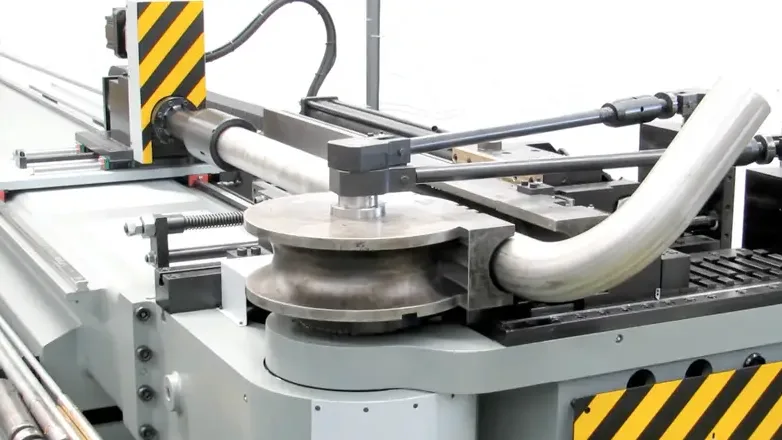
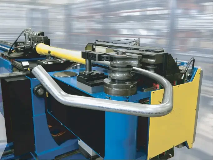
Most precision bent tube, from roll cages and handrails to hydraulic lines and furniture frames, is made on a rotary draw bender. Four tools do the work. The bend die is a grooved wheel whose radius sets the bend radius. The clamp die pins the tube against the bend die. As the bend die rotates, it pulls the tube around itself, while the pressure die holds the tube against the groove behind the bend. For tight radii or thin walls, a mandrel sits inside the tube at the point of bend and a wiper die sits on the inside of the bend to keep the wall from collapsing or wrinkling.
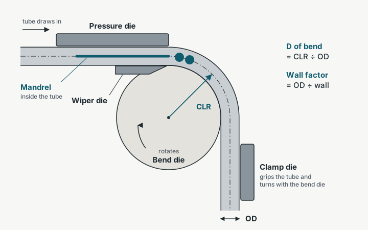
That setup explains nearly every tube bending rule. The radius is fixed by a physical die, so it is not a free variable. The clamp needs straight tube to hold. And the tube's outside wall is stretched while the inside wall is squeezed, so thin walls on tight bends are where parts fail.
Other methods exist. Roll bending makes large sweeping arcs, such as curved railings and architectural frames, without a fixed die radius. Compression and ram bending are faster and cheaper but leave more distortion. If your part is a gentle arc rather than a set of discrete bends, say so: it may belong on a roll bender, not a rotary draw machine.
Radius: pick one the shop already owns
The bend radius on a tube is measured to the centerline of the tube and called the centerline radius, or CLR. Shops also describe it relative to the tube's outside diameter (OD) as the D of bend: a 1.5 in OD tube bent on a 3 in CLR is a 2D bend.
Every combination of tube OD and CLR needs its own bend die set. A shop that already owns the die can run your part as soon as it is programmed. A shop that does not has to buy or make one, which adds a tooling charge and lead time. That makes the radius the single biggest cost lever in a bent tube design.
Three habits keep it cheap:
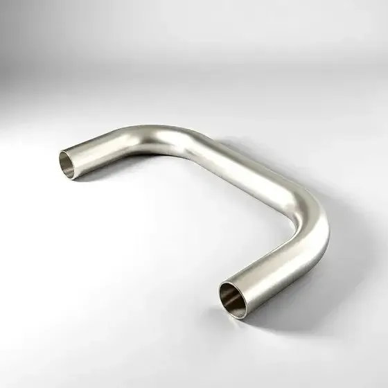
- Use one radius for every bend on the part. Each extra radius means another die set and, on most machines, another setup. Multi-stack tooling can carry two or three radii on one machine, but not every shop has it for your size.
- Design to a common radius. For most tube sizes, 2D and 3D radii are widely stocked. Ask the shop for its die list, or see the common CLRs by tube size in our tube bend radius chart.
- Dimension the CLR, not the inside radius. The die is specified by centerline radius. An inside radius on the drawing forces the shop to convert, and a rounding difference can point to a die that does not exist.
Tighter than 2D is possible and common in exhaust and aerospace work, but it moves you into mandrel territory, covered next.
Wall thickness: when you need a mandrel
When a tube bends, the outside of the bend stretches and thins and the inside compresses and thickens. Make the radius too tight for the wall and the inside wrinkles, the outside flattens, or the cross-section collapses into an oval.
Shops judge how hard a bend is with two ratios. D of bend is CLR divided by OD. Wall factor is OD divided by wall thickness. A small D of bend and a large wall factor, meaning a tight radius on a thin wall, is the hard case.
As a rough guide, a 3D or larger bend in tube with a wall factor under about 10 can often be bent with no mandrel at all. Somewhere around 2D, or wall factors in the 10 to 20 range, a plug or single-ball mandrel usually becomes necessary. Below 2D with thin walls, expect a multi-ball mandrel and a wiper die.
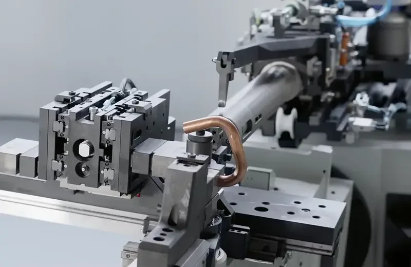
Those boundaries move with the material, the machine and the shop's experience, which is why the reference chart presents them as starting points rather than limits.
Mandrel bending is routine, but it adds tooling, lubrication, setup time and a slower cycle. If you have a choice between opening the radius, adding wall thickness or accepting a mandrel, say which you prefer on the RFQ. A shop can quote the cheapest one only if it knows the others are allowed.
The outside wall also gets thinner. A useful idealized estimate is that the outer wall thins by about 1 / (2D + 1) of its original thickness: roughly 33 percent at 1D, 20 percent at 2D and 14 percent at 3D. In practice the shift of the neutral axis and pressure die boost usually keep it below that, but if the tube carries pressure, check the thinned wall, not the nominal one.
Straight length: give the clamp something to hold
Between two bends, the clamp die has to grip straight tube. Clamp length varies by machine and tube size, but plan on at least 1.5 to 2 tube diameters of straight between the end of one bend and the start of the next. Under about one diameter, most clamps cannot hold the tube, and the shop has to make a short or special clamp, bend the part in two pieces and weld it, or ask you to change the design.
The same applies at the ends. The first bend needs clamp length behind it, and many shops bend from a longer blank and trim the ends afterward. If an end length is critical, mark it, and expect the shop to cut to length after bending rather than before.
Bends that run directly into each other with no straight between them, sometimes called bend on bend or compound bends, can be made with special tooling or by bending in a different order, but they are a quoting question, not a default. Flag them.
Springback, ovality and the tolerances you can hold
Springback. After the bend die releases, the tube relaxes and opens up by a few degrees. The machine compensates by overbending, and CNC benders store a correction per material and size. Stainless steel and harder alloys spring back more than mild steel or soft aluminum, and the correction is dialed in on the first parts, which is one reason first articles matter more in tube work than in many other processes.
Ovality. A round tube comes out of a bend slightly oval. The cross-section flattens in the plane of the bend, so the diameter measured toward the bend center shrinks and the diameter across it grows. A mandrel keeps it closer to round. If a fitting, sleeve or mating part has to slide over the bend area, state an ovality limit as a percentage of OD, so the shop knows whether a mandrel is required.
Tolerances. Bend angle on a CNC rotary draw bender is commonly held to about plus or minus half a degree to one degree, and lengths between bends to roughly plus or minus 0.5 to 1.5 mm, though both depend on the shop, the material and the part. The bigger effect is accumulation. A part with six bends stacks six angle errors and six length errors, and the far end can land several millimeters from nominal even when each bend is in tolerance. If two ends must meet a mating part, dimension them to each other and say so, so the shop can control the sequence around that requirement and check it on a fixture.
Material choices that make bending easier
Mild steel. Bends well. DOM (drawn over mandrel) tube has a more uniform wall and a cleaner seam than ERW (electric resistance welded) tube, so it is the usual choice for tight bends and structural parts such as roll cages. With ERW, the weld seam is best placed near the neutral axis of the bend, so mention it if seam position matters.
Stainless steel. 304 and 316 bend well but work harden, spring back more and gall against tooling without good lubrication. Expect a mandrel at tighter radii and slightly more setup.
Aluminum. Temper matters more than alloy. 6061-T6 is strong but cracks on tight bends; a 3D radius or larger is a safer default, or the part can be bent in a softer temper and heat treated afterward. 6063, 3003 and 5052 bend far more easily. The same trade-off is covered for flat parts in 6061 vs 7075 aluminum.
Copper and brass. Bend easily when annealed, which is why they dominate plumbing and heat exchanger work. Thin walls kink, so the wall factor rules still apply.
Titanium. Grade 2 bends cold with care. Grade 5 is much harder to form and usually needs a larger radius or heat.
Tube or pipe. Tube is sized by its real outside diameter and wall. Pipe is sized by a nominal pipe size and schedule, and a 1 in pipe has an outside diameter of 1.315 in. Bend dies are made to the real OD, so give the actual OD and wall, or the exact pipe size and schedule, never just a nominal number.
Holes, slots and finishing: order of operations
Bending moves material, so anything machined into the tube before bending can move with it. A hole near a bend can stretch into an oval, and a precise hole pattern can end up out of position once the part springs back.
The rule of thumb is to bend first and machine critical features after, on the straight sections, using a fixture that locates off the bent part. Noncritical holes and notches can be laser cut or punched into the straight tube before bending to save cost, as long as they sit well clear of the bend zone. Tube laser cutting before bending is common for production parts for exactly this reason.
Welding, coating and plating follow bending. Powder coating is the usual finish for steel frames, and a coated part adds thickness wherever it mates with something else. For how coatings eat into fits, see how surface finish changes your tolerances.
The rules, in one table
Use these as a check against your model. Each one points back to a physical limit of the bender, so a shop may relax any of them for a specific part if you ask.
| Feature | Guideline | Why |
|---|---|---|
| Bend radius | One CLR for every bend, ideally 2D to 3D | Each radius needs its own die set |
| Radius callout | Dimension the centerline radius | Dies are specified by CLR |
| Tight radius or thin wall | Below about 2D, or wall factor above about 20, expect a mandrel | Prevents wrinkling, flattening and collapse |
| Straight between bends | At least 1.5 to 2 times OD | The clamp die needs straight tube to grip |
| End lengths | Allow trim stock or mark critical ends | Ends are often cut to length after bending |
| Critical holes | Machine after bending, on straight sections | Bending and springback move pre-cut features |
| Ovality | State a limit only where a part slides over the bend | Drives whether a mandrel is required |
| Tube size | Give actual OD and wall, or exact pipe size and schedule | Dies are made to the real outside diameter |
Starting points for rotary draw bending. Limits move with material, machine and tooling, so ask the shop where your part sits.
What to send for a tube bending quote
A 3D model. A STEP file of the bent part, with the tube modeled as tube, lets the shop extract the bend data directly. Many tube CAD tools and bender programs read STEP centerlines without retyping. If you work only in 2D, give the bend data as either XYZ coordinates of the centerline intersection points or as a length, rotation and angle table (often called YBC or LRA), with the CLR for each bend.
A reference drawing with it. Send a PDF engineering drawing alongside the CAD file. A STEP file carries geometry only: it does not say which dimensions are critical, what tolerance each one needs, the material and temper, ovality limits, end preparation, hole callouts or finish. The drawing does, and it is what the shop inspects the first article against. A model without a drawing gets quoted to the shop's default tolerances, which may not be yours. See what CAD files to send for a quote for the general version of this.
Tube size, material and condition. Actual OD, wall thickness, alloy and temper, and DOM or ERW for steel. Note any requirements about seam position, mill certs or material certifications.
What matters most. Name the dimensions that must hold, such as end-to-end position or the fit to a mating part, and the ones that can float. That tells the shop where to put its inspection effort.
What else happens to the part. End forming, notching, holes, welding and finish all affect the quote and the sequence. Put them on the drawing rather than in a follow-up email.
On OpenSpindle, upload the STEP on the quote page, attach the drawing on that part's card under Reference Files & Technical Drawings, and say in the part note that it is bent tube. A matched partner shop reviews the bends against its tooling and you get one quote back, usually in about 24 hours.
Last reviewed by Tom Petrini